-")

Description
Main Features
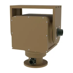
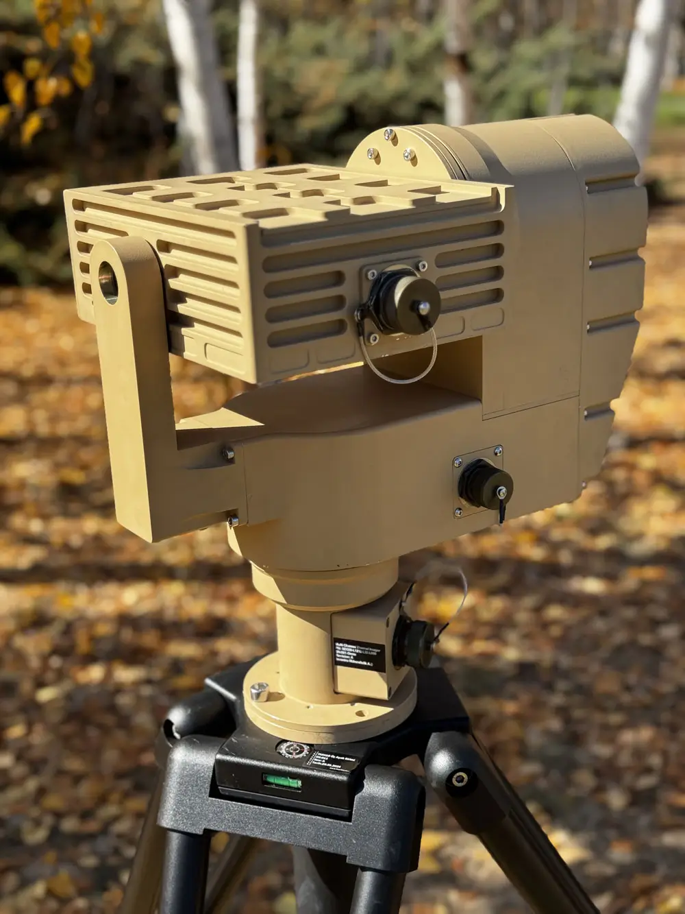
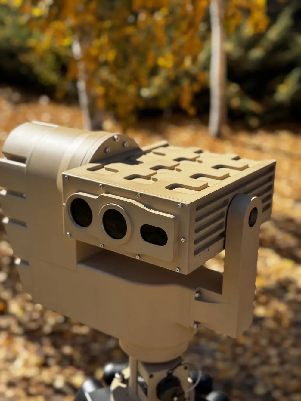
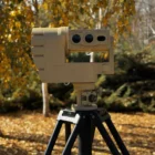
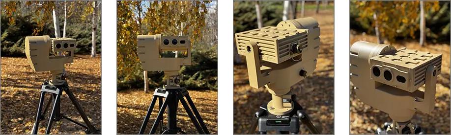
The PED08 provides a combination of controllability, positional accuracy, and price/performance ratio, making it suitable for fixed installations as well as light vehicle applications. It features MIL-STD-461F EMI/EMC compliance, making it suitable for installations across diverse environments, including ground-based and light vehicle-mounted setups.
Distinctive Features
True Servo Drive System: Utilizes brushless motors, enhancing accuracy over stepper motors.
Ultra-Low Power Consumption: Operates at 10W with “Smart Driving Mode” for efficiency.
Active Disturbance Rejection: MCU actively counters external interference for steady operation.
High-Resolution Positioning: 22-bit encoders provide precise positioning and control.
MIL-STD-461F Compliant: EMI/EMC standards ensure resilience in demanding environments.
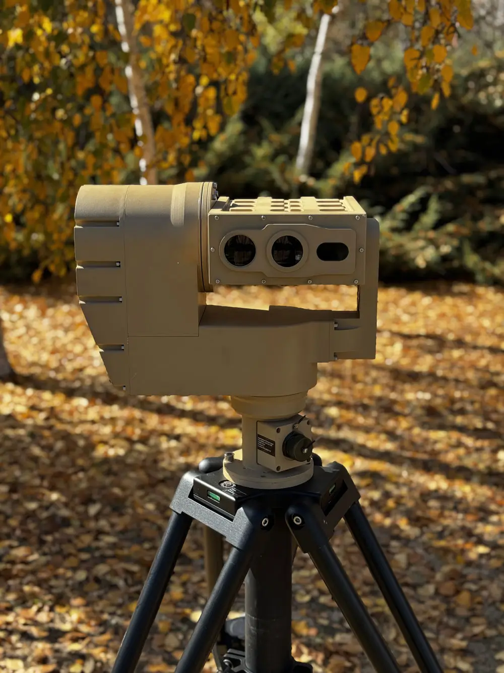
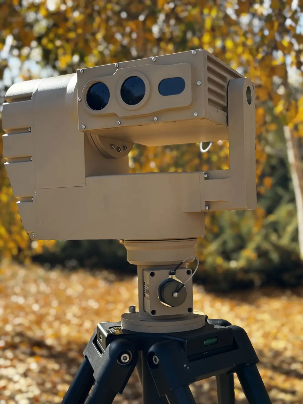
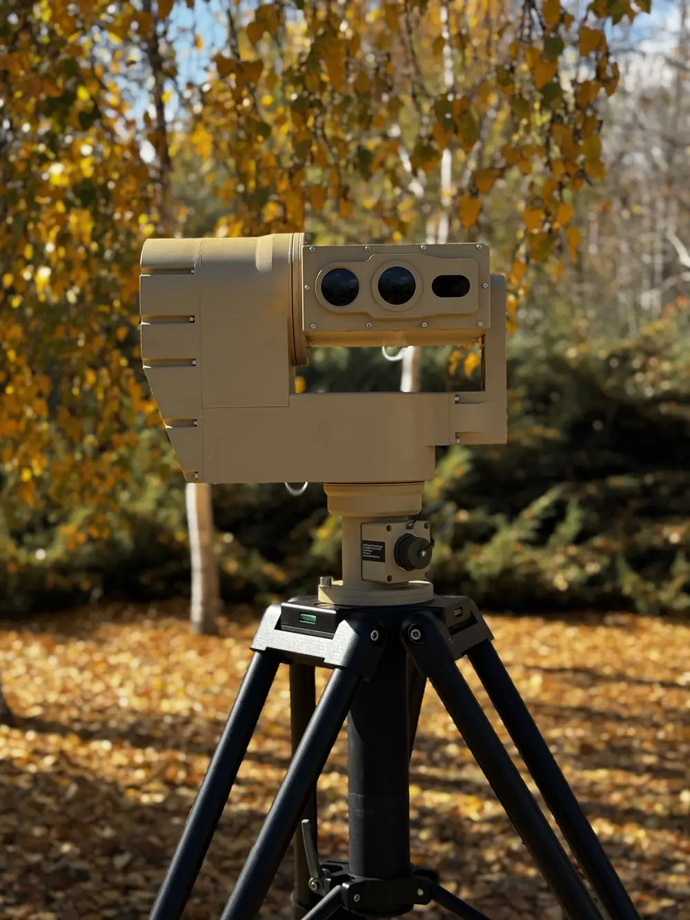
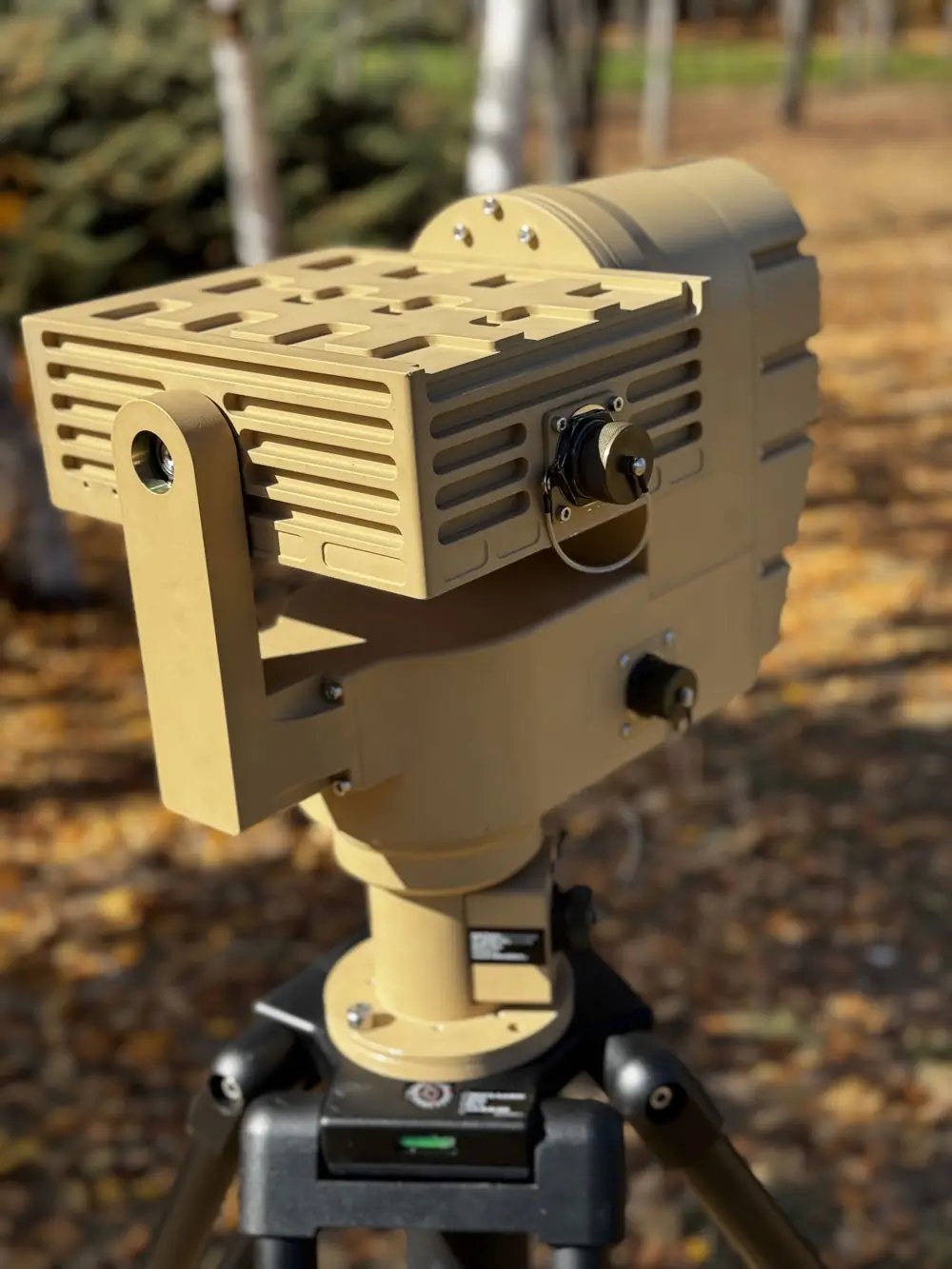
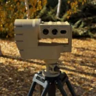
Tripod Compatibility: Mounts on TMH or TMM tripods for versatile field deployment.
Coastal and Seaborne Customization: Options tailored for marine environments
A. High-Resolution Positioning
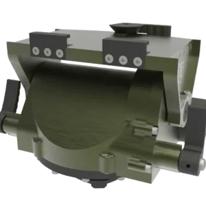
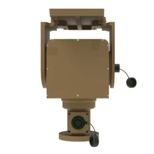
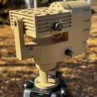
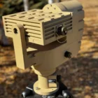
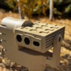
B. Compact, Lightweight Design
C. Tripod-Compatible
D. Brushless Servo Motors
Specifications
| PED12 – PX – ABX
Speed/Torque Configuration Breakdown |
||
| PED10 | PX – Pan Axis Speed/Torque Conf. | ABX – Tilt Axis Speed/Torque Conf. |
| Positioner – Electromechanical – Dual Axis | Any “A type” configuration is applicable | Any “A type” or “B type” configuration is applicable |
| Speed/Torque Configuration | A1 | A2 | A3 | A4 | B1 | B2 | |
| Nominal Speed (°/s) | 28 | 48 | 96 | 180 | 28 | 48 | |
| Nominal Torque (Nm) | 185 | 150 | 80 | 60 | 275 | 175 | |
| Peak Torque (Nm) | 225 | 215 | 120 | 100 | 475 | 450 | |
| Momentary Peak Torque (Nm) | 400 | 400 | 360 | 250 | 875 | 875 | |
- Nominal Speed / Nominal Torque represents operation range with %100 duty cycle.
- Peak Torque represent limits for acceleration and deceleration limits.
- Momentary Peak Torque represent limits impulsive shock limits device can absorb.
| Parameters / Configurations | PED12-A2-A1 | PED12-A4-A1 | PED12-A1-B1 | ||||
| Pan – Peak Torque (Nm) | 215 | 100 | 225 | ||||
| Pan –Torque (Nominal) (Nm) | 150 | 60 | 185 | ||||
| Pan – Speed (Nominal) (°/s) | 48 | 180 | 28 | ||||
| Tilt – Peak Torque (Nm) | 225 | 225 | 475 | ||||
| Tilt – Torque (Nominal) (Nm) | 185 | 185 | 275 | ||||
| Tilt – Speed (Nominal) (°/s) | 28 | 28 | 28 | ||||
| Pan – Axis Range (°) | N x 360° | ||||||
| Tilt – Axis Range (°) | Up to ±45° | ||||||
| Resolution (°) | 0.002 | ||||||
| Accuracy (°) | 0.038 | 0.032 | 0.028 | ||||
| Operating Voltage (VDC) | 18-48 | ||||||
| Weight (kg) | 16.1 | 16.1 | 17.5 | ||||
| Communication to the Unit | Ethernet, RS-485, RS422 (Full Duplex), USB | ||||||
| Connector Type | MIL-DTL-38999 | ||||||
| Slipring | Up to 76 lines including (1 Gbit Ethernet, RS422, RS232, HD-SDI) | ||||||
| Stabilization | Available | ||||||
| Dual-Loop Control | Position Control at the Order of 0.001° with Secondary Encoder | ||||||
| Hand Controller | Available | ||||||
| Multiple Payload Interface | Available | ||||||
| Width (A) (mm) | 430 | ||||||
| Height (B) (mm) | 445 (depends on slipring configuration) | ||||||
| Depth (C) (mm) | 270 | ||||||
| Wind Load (km/h) | 120 | ||||||
| IP Rating | IP65 | ||||||
| Temperature (°C) | MIL-STD-810G, Method 502.5 Procedure II – Operational, -32°C
MIL-STD-810G, Method 501.5 Procedure II – Operational, +60°C MIL-STD-810G, Method 501.5 Procedure I – Storage; +70°C MIL-STD-810G, Method 502.5 Procedure I – Storage; -40°C |
||||||
| Low Pressure | MIL-STD-810G, Method 500.5 Procedure I – Storage 37,000ft
MIL-STD-810G, Method 500.5 Procedure I – Operational 10500ft |
||||||
| Vibration | MIL-STD-810G, Method 514.6 Procedure I Category 20, Figure 514.6C-3 | ||||||
| Shock | MIL-STD-810G, Method 516.6 Functional Shock, 20G 11ms, XYZ Axis, 3 Positive and 3 Negative Each Axis | ||||||
| Humidity | MIL-STD-810G, Method 507.5 Procedure I – %90 Noncondensing @60°C, 11 Days | ||||||
| Rain | MIL-STD-810G, Method 506.5 Procedure II | ||||||
| Salt Fog | MIL-STD-810G, Method 509.5, 2 Cycles of 24 Hours | ||||||
| Dust and Sand | MIL-STD-810G, Method 510.5, Procedure I and Procedure II | ||||||
| EMI/EMC Compliancy | CE102 – Conducted Emissions, Power Leads
CS101 – Conducted Susceptibility, Power Leads CS114 – Conducted Susceptibility, Bulk Cable Injection CS115 – Conducted Susceptibility, Bulk Cable Injection CS116 – Conducted Susceptibility, Damped Sinusoidal Transients CS118 – Conducted Susceptibility, Personnel Borne ESD RE102 – Radiated Emissions, Electric Field RS103 – Radiated Susceptibility, Electric Field |
||||||
*Refer to Datasheet
Ordering Information
| Configuration Breakdown | Positioner – Electromechanical – Dual Axis – 12 (Product Class) – Pan Speed/Torque – Tilt Speed/Torque |
| Part Number | PED12-AX-ABX (Check Available Options Below) |
| Available Customizations | Communication Protocol, Output Speed, Output Torque, Number of Slipring Lines, Mechanical Interfaces |
| Combinable Platforms | SEBXX – Multi Channel Thermal Imager
MES10 – Locked Electromechanical Mast Platform MEM10 – Ultra-Stable Electromechanical Mast Platform TMH10 – Heavy Duty Tripod |